
A well-prepared foundation plan is one of the most critical documents in any construction project. From residential homes to large commercial structures, this plan defines how a building transfers its load safely to the ground. As a specialist in construction documentation and digital workflows, I’ve seen firsthand how a clear, accurate foundation layout can prevent costly structural issues, delays, and miscommunication across teams.
In today’s construction environment, where precision, coordination, and efficiency are non-negotiable, understanding how these plans work is no longer optional. Whether you’re a contractor, architect, engineer, or property owner, this guide will walk you through every essential aspect in a practical, experience-driven way.
Table of Contents
What is a Foundation Plan?
A foundation plan is a precise technical drawing that defines how the structural base of a building will be constructed and positioned on the site. It serves as a direct guide for engineers, contractors, and construction teams to translate design concepts into real-world execution.
At its core, this plan answers several critical questions:
- Where exactly will structural elements be located on the site
- What type of foundation system will be used
- How will loads from the building transfer safely into the ground
- How do different structural components connect and work together
Unlike architectural drawings that focus on layout and aesthetics, a foundation plan is entirely focused on structural performance and stability. It provides detailed information about:
- Footings (size, depth, and type)
- Foundation walls and slabs
- Columns and piers
- Reinforcement details
- Elevation references and grid lines
One of the most important aspects of this plan is that it is site-specific. The design is influenced by factors such as:
- Soil conditions and bearing capacity
- Groundwater levels
- Building load requirements
- Environmental and seismic considerations
This means even similar buildings can have completely different foundation designs depending on where they are built.
From a practical perspective, this drawing is used on-site to accurately set out the building before construction begins. It ensures that every structural element is placed in the correct position, at the correct depth, and built according to engineering specifications.
In modern construction workflows, integrating foundation plans with BIM modeling services enhances accuracy by allowing teams to visualize the structure in 3D, detect potential conflicts early, and improve coordination across disciplines.
Essential Components Found in a Foundation Drawing
A well-prepared foundation drawing includes several key components that guide both design understanding and on-site execution. Each element plays a specific role in ensuring structural stability and construction accuracy.
- Footings: Footings are the base elements that transfer the building load to the soil. The plan specifies their size, depth, and type to ensure proper load distribution and prevent settlement issues.
- Foundation Walls: These walls support the structure above and may also retain soil in below-grade areas. The drawing defines their thickness, location, and connection to footings.
- Columns and Piers: Columns and piers act as vertical load-bearing elements. Their exact positions and dimensions are clearly marked to ensure proper alignment with the structural system above.
- Slabs: Slabs form the base surface of the structure, such as slab-on-grade foundations. The plan includes thickness, reinforcement, and elevation details.
- Reinforcement Details: Reinforcement (rebar) is essential for structural strength. The drawing indicates bar size, spacing, and placement to ensure the foundation can handle tension and load stresses.
- Grid Lines and Reference Points: Grid lines act as a positioning system for the entire structure. They help contractors accurately locate all elements on-site and ensure alignment with other drawings.
- Elevations and Section Markers: Elevation markers show height levels, while section cuts provide deeper insight into how elements are constructed below the surface. These are critical for understanding depth and vertical relationships.
When coordinated with MEP BIM services, these components are also checked against mechanical, electrical, and plumbing systems to prevent conflicts during construction.
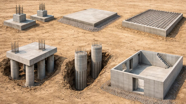
What are the Types of Foundation Plans?
Different projects require different foundation systems depending on soil conditions, structural loads, and project requirements. Below are the most common types, each with a clear and practical explanation:
Spread Footing Foundation
This is one of the most widely used foundation types, especially in residential construction. Individual footings are placed under columns or load-bearing walls to spread the load over a larger area.
- Suitable for stable soil with good bearing capacity
- Cost-effective and relatively simple to build
- Not ideal for weak or highly compressible soils
Slab-on-Grade Foundation
A concrete slab is poured directly on the ground and acts as both the foundation and the floor of the structure.
- Common in warm climates with minimal frost depth
- Faster construction and lower overall cost
- Limited access to utilities after construction
Mat (Raft) Foundation
A thick, continuous slab supports the entire building footprint, distributing loads evenly across the ground.
- Ideal for soft or low-strength soils
- Helps reduce differential settlement
- Requires more material and careful structural design
Pile Foundation
Long vertical elements are driven deep into the ground to transfer loads to stronger soil layers or bedrock.
- Used for heavy structures or poor surface soil conditions
- Provides high load-bearing capacity
- Requires specialized equipment and a higher cost
Pier (Drilled Shaft) Foundation
Constructed by drilling holes into the ground and filling them with reinforced concrete.
- Suitable for sites with variable soil conditions
- Provides strong support with fewer elements than piles
- Requires precise engineering and execution
Basement Foundation
Includes a full or partial basement that serves as part of the structural foundation.
- Adds usable space to the building
- Common in colder regions
- Higher construction and waterproofing costs
Each of these foundation types has its own strengths and limitations. Selecting the right system depends on a careful evaluation of soil conditions, load requirements, and project goals. In modern workflows, tools like BIM coordination services help simulate performance and improve decision-making before construction begins.
How to Draw a Foundation Plan
Drawing a foundation plan requires careful planning, technical knowledge, and attention to detail. Here’s a step-by-step approach that ensures accuracy and practical usability on-site:
Step 1: Gather Site and Structural Data
Start by collecting all necessary information about the project: soil test reports, building load calculations, environmental considerations, and architectural layouts. This data sets the foundation for making informed design decisions.
Step 2: Choose the Appropriate Foundation Type
Based on soil conditions, load requirements, and project goals, decide which type of foundation is most suitable. Options include spread footings, slab-on-grade, mat foundations, piles, piers, or basement foundations. Consider cost, constructability, and performance.
Step 3: Layout Grid Lines and Reference Points
Establish a grid system that aligns with the architectural plan. Grid lines and reference points help position footings, walls, columns, and slabs accurately, reducing potential errors during construction.
Step 4: Define Footings, Columns, and Piers
Mark the locations, dimensions, and depth of all footings, columns, and piers. Include reinforcement details and any structural connections that ensure safe and efficient load transfer is safe and efficient.
Step 5: Draw Slabs and Foundation Walls
Illustrate slab thickness, elevation levels, and wall placements. Make sure all elements are aligned with the grid and structural requirements. Annotate any sections that require special attention, such as load concentration points.
Step 6: Add Reinforcement and Structural Details
Specify rebar size, spacing, and placement. Clearly indicate section views or detail callouts where additional construction guidance is needed. Reinforcement ensures the foundation can withstand tension and compression forces effectively.
Step 7: Review and Coordinate with Other Systems
Check the foundation layout against mechanical, electrical, and plumbing requirements. Leveraging modern digital coordination tools can help detect and resolve potential conflicts between structural and building systems before construction begins.
Step 8: Verify and Finalize the Plan
Double-check all dimensions, annotations, and notes. Align the drawing with project scheduling and construction workflows to ensure the project progresses smoothly and accurately. Leveraging BIM tools can help streamline coordination among teams and reduce errors during implementation.
By following these steps, engineers and contractors can produce a clear, accurate, and practical foundation plan that serves as a reliable guide throughout the construction process.

How to Accurately Read and Interpret Structural Drawings
Reading a foundation plan is a step-by-step process that combines an understanding of technical symbols with practical on-site application. Here’s how to approach it effectively:
Step 1: Understand the Legend and Symbols
Start by reviewing the legend carefully. This part of the drawing explains what each symbol, line type, and abbreviation means. Knowing these allows you to quickly identify footings, columns, slabs, and reinforcement details without confusion.
Step 2: Check the Scale and Dimensions
Next, pay attention to the scale of the drawing. This helps you translate measurements from the plan to real-world dimensions. Make sure to verify key sizes such as footing widths, slab thickness, and column locations so that everything aligns correctly during construction.
Step 3: Review Grid Lines and Reference Points
Grid lines and reference points provide a framework for locating all structural elements. They act like coordinates, guiding where footings, walls, and columns should be placed on the site. Understanding these points reduces mistakes and ensures consistency with other plans.
Step 4: Examine Section Views and Detail Callouts
Section views show vertical information like depth, reinforcement, and how different components connect. Detail callouts highlight critical construction instructions that aren’t obvious in the top-down plan. Paying close attention here helps prevent structural errors.
Step 5: Cross-Check with Modern Tools
Finally, using modern tools such as laser scan-to-BIM services can make interpreting drawings even easier. These tools allow teams to compare the design directly with actual site conditions, identify potential issues early, and ensure that what is built matches the plan precisely.
By following these steps, anyone from engineers to contractors can confidently read and interpret a foundation plan, ensuring accuracy and minimizing costly errors.

Comparing Floor Plans, Structural Plans, and Basement Layouts
It’s common for people to confuse floor plans, structural plans, and basement layouts, but each serves a distinct purpose in a construction project. Understanding their differences is crucial to avoiding mistakes, conflicts, and delays during construction.
Floor Plans
Floor plans focus on the layout of a building’s interior spaces. They show the arrangement of rooms, doors, windows, hallways, and furniture placement. Essentially, they represent how people will move and use the space above ground. Floor plans rarely include detailed information about structural support unless it intersects with walls or columns.
Structural Plans
Structural plans (or foundation plans) provide detailed information about load-bearing elements that support the building. This includes footings, foundation walls, columns, piers, slabs, and beams. The goal of structural plans is to ensure the building’s weight is safely distributed to the ground. They also include reinforcement details, section views, and critical dimensions that the construction team must follow exactly.
Basement Layouts
Basement plans combine elements of both floor and structural plans. They show usable space, walls, staircases, and mechanical rooms, while also including foundation walls, footings, and slab details. Because basements exist below ground, their layout must carefully integrate both structural support and functionality, making coordination with structural plans essential.
How They Work Together:
These plans are interconnected:
- Columns or walls shown in a structural plan must align with walls and partitions in the floor plan.
- Staircases and mechanical shafts in a basement layout need to match both structural and floor plans.
- Misalignment between these plans can lead to construction errors, rework, and added costs.
Modern construction workflows often use digital tools like BIM-to-field layout to translate these designs into precise on-site positions. This ensures that what is designed in 2D or 3D accurately corresponds to the real-world construction.
| Feature/Plan Type | Floor Plan | Structural Plan | Basement Layout |
|---|---|---|---|
| Main Focus | Spatial layout and circulation | Load-bearing elements and support | Combination of structure & usable space |
| Elements Shown | Rooms, doors, windows, furniture | Footings, columns, walls, slabs, reinforcement | Walls, foundation, footings, mechanical rooms |
| Level of Detail | Moderate | High (technical and structural) | High (structural + functional) |
| Coordination Requirement | Moderate | Critical | Very high (requires both floor & structural alignment) |
| Use in Construction | Guides interior layout | Guides construction of foundation and load support | Guides construction of basement and below-ground structure |
By understanding the differences and relationships between these three types of drawings, contractors and project managers can avoid conflicts, ensure proper alignment, and execute the project more efficiently.
Common Errors That Can Lead to Costly Construction Issues
Even small mistakes in foundation plans can cause major problems on a construction project. Understanding these errors in advance helps engineers, contractors, and project managers avoid costly delays and rework. Here are the most frequent types of errors:
- Incorrect Soil Assumptions: Assuming the soil is uniform or stronger than it actually is can lead to settlement, cracks, or even structural failure. Always verify soil tests and consult with geotechnical engineers to ensure the foundation is suitable for the site conditions.
- Poor Coordination Between Systems: Conflicts between structural elements and mechanical, electrical, or plumbing systems (MEP) are a common source of construction delays. For example, a footing might clash with underground plumbing if not coordinated early. Using MEP BIM services during planning can help detect these conflicts before construction begins.
- Inaccurate Dimensions and Measurements: Errors in footing widths, slab thickness, or column placement can cause misalignment with the rest of the structure. Even small deviations can have a domino effect, impacting walls, floors, and ceilings above. Double-check all dimensions against plans and cross-reference with site conditions.
- Missing or Incomplete Reinforcement Details: Rebar placement, spacing, and sizing are critical for structural strength. Missing or vague reinforcement details can weaken the foundation and compromise safety. Always ensure drawings include complete reinforcement instructions.
- Unclear Annotations or Notes: Ambiguous symbols, abbreviations, or missing labels can lead to misunderstandings on-site. Clear, precise annotations prevent mistakes and reduce the need for clarification during construction.
- Rushed Design and Lack of Collaboration: Many errors stem from a design process that is rushed or poorly coordinated among architects, engineers, and contractors. Integrating construction project scheduling services early ensures that design, coordination, and execution timelines are aligned, reducing the risk of errors and costly revisions.
By being aware of these common errors and implementing proper planning, review, and coordination, construction teams can prevent major issues and ensure a smooth foundation installation.
Choosing the Most Suitable Foundation Strategy for Your Project
Selecting the right structural system requires a balance of engineering analysis, site conditions, and project goals. Soil testing is the first step, as it determines the bearing capacity and stability of the ground. From there, engineers evaluate load requirements and environmental factors to recommend the most suitable option.
Equally important is the integration of planning and execution strategies. A well-defined BIM execution plan for contractors ensures that all stakeholders, from designers to builders, are aligned from the beginning. This not only improves efficiency but also reduces risks associated with miscommunication and design changes.
The Role of Technology in Modern Foundation Planning
Construction has evolved far beyond traditional 2D drawings. Today, digital tools and data-driven workflows are transforming how foundation systems are designed and executed. Building Information Modeling allows teams to visualize the entire structure, simulate performance, and identify potential issues before construction begins.
This shift toward digitalization is not just about efficiency; it’s about accuracy and risk reduction. By leveraging advanced modeling and coordination tools, project teams can deliver higher-quality outcomes while minimizing delays and unexpected costs.
Conclusion
A well-designed foundation plan is more than just a technical drawing; it is the backbone of a successful construction project. From ensuring structural stability to enabling seamless coordination across disciplines, its importance cannot be overstated. By understanding its components, avoiding common mistakes, and leveraging modern technologies, you can make informed decisions that lead to safer, more efficient, and more cost-effective construction outcomes.
FAQs
What type of drawing is a foundation plan?
A foundation plan is a technical drawing focused on the structural base of a building. It illustrates footings, columns, slabs, and other load-bearing elements, providing precise information for safe construction and proper load distribution.
Why is soil analysis important for a foundation plan?
Soil conditions determine the type and depth of the foundation required. Testing soil ensures the foundation can safely support the building load and prevents issues such as settlement, cracking, or structural failure.
Can the same building design have different foundation plans?
Yes. Even if the architectural design is identical, factors like soil type, groundwater level, and environmental conditions can require different foundation systems and layouts for each site.
Are foundation plans used for remodelling projects as well?
Absolutely. For renovations or additions, foundation plans help engineers and contractors understand load paths, identify structural limitations, and plan modifications safely.
Add a Comment