
Understanding the concept of reduced level is essential for anyone involved in construction, surveying, engineering, or BIM-based project delivery. In simple terms, reduced level (RL) refers to the height or elevation of a point relative to a predefined reference benchmark. This measurement is critical for determining the precise vertical alignment of a structure, setting out levels on site, controlling excavation depths, validating as-built conditions, and ensuring that a project meets planned design elevations. Whether you are evaluating earthwork volumes, checking slab levels, or integrating measured data into BIM workflows, RL is one of the most fundamental metrics used throughout the construction lifecycle.
Table of Contents
Understanding Reduced Level (RL): A Practical Concept in Site Surveying
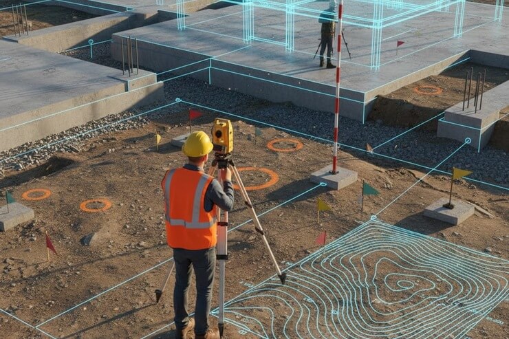
Reduced level is a foundational concept in surveying that helps determine the vertical position of any point on a construction site. Surveyors use RL to understand how high or low a point is compared to a benchmark or datum line, which typically represents an agreed-upon elevation such as sea level or a local reference mark.
In practical fieldwork, RL is measured using tools like leveling staffs, optical levels, auto-levels, digital levels, and total stations. The measurement process involves establishing a known benchmark and calculating the height of the instrument (HI), then determining the RL of other points using back sight (BS) and fore sight (FS) readings. In modern workflows, RL forms the backbone of earthworks design, drainage layouts, foundation depth calculations, and vertical alignment of structural elements.
More importantly, RL data serves as a bridge between traditional field surveying and digital construction tools, enabling teams to validate existing site conditions and support advanced modeling practices
How Reduced Level Is Applied in Construction Projects
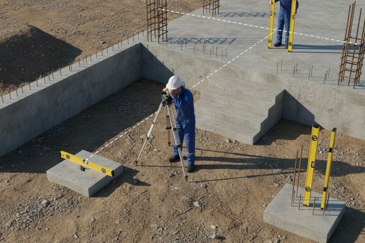
Reduced level is used at almost every stage of construction planning and execution. In excavation works, RL determines how deep the soil must be cut or filled to reach design levels. For foundation construction, RL ensures that footings are placed at the correct depth, maintaining structural integrity and preventing future settlement issues.
In structural work, RL guides the vertical placement of columns, beams, and slabs. Surveyors constantly check RL to ensure that floor levels match the design drawings, especially in high-rise buildings where even minor deviations can accumulate and cause significant geometric misalignment.
RL is also essential for drainage and road construction. Roads must maintain precise gradients for proper runoff, while drainage lines rely on RL to ensure flow direction and prevent blockages. Mechanical, electrical, and plumbing (MEP) installations also use RL to set the height of pipes, ducts, and services, preventing clashes and ensuring the systems function efficiently.
How Reduced Level Appears in Engineering Drawings and Site Plans
Engineering drawings represent reduced levels using standardized symbols, abbreviations, and notation styles. Typically, RL values appear next to critical points such as slab corners, beam soffits, roof levels, finished floor levels (FFL), and ground elevations.
For example:
- RL 0.000 may represent the main building datum
- RL +3.500 may indicate the first floor level
- RL -1.200 may denote a basement or excavation depth
In plan views, RL values help contractors understand how different parts of the structure relate vertically to one another. In section drawings, RL is used to show the vertical position of foundations, plinth beams, staircases, ramps, and roof profiles.
Being able to read RL values quickly and accurately is crucial for any on-site team member, including engineers, surveyors, supervisors, and BIM technicians.
Differences Between Reduced Level and Other Surveying Measurements
Reduced level often gets confused with other elevation-based surveying terms. Understanding the differences helps eliminate errors and improve communication between site teams.
RL vs Elevation
Elevation is the height of a point above sea level or a national geodetic benchmark. RL may use the same reference, but often uses local site datums for convenience. Elevation is usually absolute, while RL can be project-specific.
RL vs Height of Instrument (HI)
HI is the vertical height of the surveying instrument relative to the benchmark. RL, on the other hand, describes the elevation of any surveyed point. HI is an intermediate value used to calculate RL.
RL vs Benchmark (BM)
A benchmark is a fixed reference point with a known elevation or RL. RL values of other points are calculated in relation to the benchmark.
RL vs Finished Floor Level (FFL)
FFL represents the design height of a completed floor surface. RL shows the actual measured height. Comparing RL and FFL helps determine if the constructed floor is at the correct level.
RL vs Cut and Fill Levels
Cut and fill represent how much soil needs to be removed or added. RL determines existing elevations, while cut/fill represents adjustments needed to achieve final levels.
Units and Measurement Systems Used for Reduced Level
Reduced level measurements are commonly expressed in:
- Meters (m) in most countries (including Canada, Europe, Australia)
- Feet (ft) in the United States and some older construction environments
RL uses decimal notation for precision, e.g.:
- RL 112.453 m
- RL 367.82 ft
The choice of units is determined by national standards, client requirements, or engineering codes.
How to Read and Interpret Reduced Levels on Site
Understanding how to interpret RL correctly is crucial for site safety and construction accuracy. Here’s a practical guide:
- Identify the benchmark (BM)
This is your reference point with a known RL - Determine the Height of Instrument (HI)
HI = RL(BM) + Back Sight (BS) - Calculate RL for new points
RL = HI – Fore Sight (FS) - Record values clearly
Field notes must include BS, FS, intermediate sight readings, and instrument setups. - Plot RL on drawings
Add the RL next to each point to ensure proper interpretation by site teams. - Verify critical levels frequently
Check RL at corners, structural nodes, and at changes in design elevation.
Consistent RL readings ensure the project stays within tolerance and aligns with design intent.
Common Mistakes When Working With Reduced Levels
Some typical errors include:
- Incorrectly reading the leveling staff
- Misidentifying the benchmark
- Recording data in the wrong column
- Failing to account for instrument movement
- Relying on poorly calibrated equipment
Modern digital surveying tools help minimize these mistakes, but field teams must maintain strict quality-control procedures regardless of the tools used.
The Role of Laser Scanning in Capturing Accurate Reduced Levels
Laser scanning is transforming the way RL is captured on construction sites. High-density point clouds allow surveyors to capture millions of data points with millimeter accuracy. This creates highly accurate digital terrain models (DTMs) and as-built surfaces.
Modern handheld laser scanning services make RL capture faster, more precise, and more repeatable than traditional leveling techniques. These solutions are especially useful in complex environments where manual leveling is difficult or where large areas need to be scanned quickly.
How Handheld Laser Scanning Improves RL Accuracy
Handheld scanners generate real-time 3D point clouds, enabling users to identify exact elevations across uneven surfaces. Unlike traditional single-point RL measurements, scanners create a continuous elevation dataset, significantly improving accuracy and reducing the chance of missing high or low spots.
Using Total Station Layout for Reliable RL Measurements
Total stations remain one of the most trusted tools for obtaining accurate RL on-site. They provide precise vertical and horizontal angles, allowing teams to verify elevations at any point with remarkable accuracy. Total stations are also fully compatible with BIM to field layout processes, ensuring seamless integration between digital models and on-site construction.
Why Total Station Is a Standard Tool for RL-Based Site Layout
Total stations support both traditional leveling and advanced digital workflows. They are essential for slab level checks, anchor bolt placements, steel column installations, and façade alignment. Modern robotic total stations allow automated measurements, reducing manpower needs and minimizing human error.
From Reduced Level Data to As-Built Models: How Scan to BIM Helps
As-built documentation is most accurate when built upon precise RL data. From floor flatness assessments to structural element verification, RL plays a vital role in generating true-to-life digital twins of buildings. Using laser scan to BIM services, RL data is combined with intelligent modeling tools to produce highly accurate 3D representations of existing conditions.
Converting RL Data Into Accurate 3D Building Models
Accurate RL readings help ensure that digital models reflect real-world vertical alignment. When RL data is merged into BIM authoring platforms, teams can compare design models with actual site conditions, identify deviations, and make timely decisions.
Integrating Reduced Level Information Into 3D BIM Modeling
BIM relies heavily on accurate spatial data. RL values help define slab edges, ramp inclines, structural heights, service elevations, and more. For BIM technicians, RL is not just a number; it’s a critical input for 3D BIM modeling services, determining how faithfully a model represents the physical asset.
How RL Enhances Model Accuracy in BIM-Enriched Workflows
Even small RL discrepancies can lead to significant coordination problems in MEP, structural, and architectural models. Ensuring consistent vertical alignment across trades helps prevent clashes and rework.
Why Accurate Reduced Level Data Is Essential for Successful BIM Workflows
RL is foundational for connecting field conditions with digital project representations. Accurate RL allows BIM teams to:
- Validate construction progress
- Align models with actual site geometry
- Support prefabrication workflows
- Improve coordination between disciplines
Without reliable RL inputs, BIM models cannot achieve the level of precision required for modern construction.
Challenges in Managing RL Data Across Large Construction Sites
Large-scale projects often span complex terrain, multiple structures, and varying datums. RL accuracy can suffer due to:
- Instrument relocation
- Weather changes
- Vibration or movement of survey markers
- Inconsistent data logging practices
How Digital Surveys Solve RL Discrepancies
Digital survey solutions, including laser scanning and robotic total stations, allow teams to capture dense RL datasets that can be validated and compared automatically. This significantly reduces human error.
Digital Transformation in RL Measurement: From Manual Leveling to Reality Capture
The construction industry is moving rapidly toward digital-first methods of capturing RL. With modern scanning tools, RL can be extracted directly from millions of scanned points, enabling a fully digital workflow from field to BIM.
When Should You Rely on Laser Scanning Instead of Manual RL Measurement?
Laser scanning should be preferred when:
- The site is too large for manual leveling
- The terrain is uneven or unsafe
- Highly detailed as-built documentation is needed
- The project requires integration with BIM models
Scanning provides faster, richer, and more reliable RL data, especially during renovation, heritage preservation, and industrial projects.
Best Practices for Combining RL Survey Data With BIM Documentation
To ensure optimal results, teams should:
- Use consistent datum references across all data sources
- Validate RL measurements at multiple checkpoints
- Compare scanned RL data with design reference planes
- Update BIM models regularly to reflect field conditions
Conclusion
The concept of reduced level is fundamental to both traditional surveying and modern BIM-based construction workflows. Whether determining excavation depths, validating floor elevations, or integrating field measurements into digital models, RL remains one of the most critical data points in project delivery. By combining traditional leveling with advanced technologies such as laser scanning, total station layout, and BIM modeling, construction teams can achieve unparalleled accuracy, reduce rework, and ensure compliance with design intent at every stage of a project. Understanding and applying RL correctly empowers professionals to make informed decisions, maintain tighter control over on-site operations, and deliver high-quality results across all phases of construction.
FAQs
What is the reduced floor level?
The reduced floor level (RFL) is the precise elevation of a floor or surface relative to a fixed reference point, used in construction and surveying to ensure accurate height and alignment.
What is reduced-level excavation?
Reduced level excavation refers to digging or grading the ground to a specific elevation based on RL measurements, ensuring accurate depth and alignment on a construction site.
What is the difference between the relative level and the reduced level?
Relative level measures height differences between two points, while reduced level (RL) indicates a point’s exact elevation relative to a fixed reference or datum.
How do you calculate the reduced level?
Reduced level (RL) is calculated using a known reference point (benchmark) and measuring height differences with leveling instruments, applying either the rise-and-fall or height-of-instrument method.
What is the difference between RL and FFL?
RL (Reduced Level) is the exact elevation of any point relative to a fixed datum, while FFL (Finished Floor Level) specifically refers to the final surface level of a floor in a building.
Add a Comment